![]()
|
|
|
|---|
Just for the sake of having it, neither I nor this site have any affiliation with Lego, Lego group, Lego systems or Lego MindStorms. Also, I am not responsible for any damage to your RCX and/or computer that may result from the use of the knowledge/designs stored on this WebSite.
In the text of my first design (the Temp
Sensor) I stated the following:
"After acquiring my MindStorm's robotic invention system
I began performing tests on the brick to see if any the theories
I had (for future sensors) were feasible. I quickly discovered
the four basic modes. (Touch, Light, Rotation & Temperature)"
For myself, one of the biggest downsides to the RCX is the lack
of input and output ports. In some of my earlier projects I attempted
to overcome this limitation by designing sensors
& motor/light blocks that allowed
more devices to function on each port. The result, unfortunately,
meant that the user had to exponentially complicate their program
code to accommodate the new motor/sensor sharing scheme. A prime
example of this is my second project (the
resister pad). My third project (the
motor/light block) was my first attempt at expanding the output
ports. While this did give you two output ports from one it was
only one direction & in "Float" mode. ("Float"
meaning 'slows to stop' and not 'stops immediately' as in "Brake"
mode.)
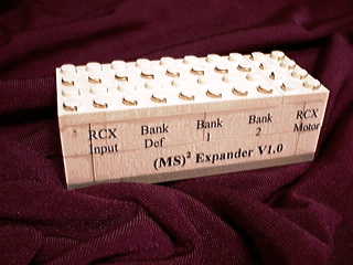
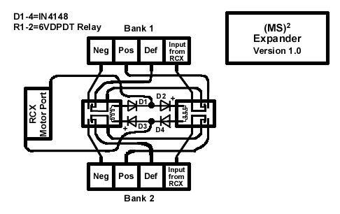
I'm very Pleased to announce that my latest project the '(MS)2
Expander' will expand your RCX's ports with very little additional
programming. Some of the possibilities are as follows;
1. 6 Full featured output ports!
(3 banks of 2 output ports with 2 usable at any one time with
full "Brake"/"Float" & Direction abilities)
2. 3 + 1 Full featured output ports & 3 + 2 Full featured
input ports!
(3 banks of 1 output port + 1 RCX direct port & 3 banks of
1 input port + 2 RCX direct ports)
3. 6 + 1 Full featured input ports! (At the loss of 1 output port)
(3 banks of 2 input ports with 2 usable at any one time + 1 RCX
direct input port)
As you will see, this device can be used simultaneously with input
& output ports with the only expense being one output port
for the controlling of the device. (The workings will be better
explained below.) Also, if you use two of the (MS)2 Expander you
can have 6 Outputs and 6 (+1 Direct) Inputs! All for the same
use of the single motor port.
Premise
First, like my last three projects (the
Temperature Sensor, the Sensor
Pad & the Motor/Light block),
this project uses the Lego Electric Plating (part #5037) for the connectors.
You will need (Parts)
You will require the following components;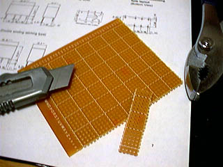
Lego components:
2x 2 by 8 electric plating (#5037)
1x 2 by 4 electric plating (#5037)
4x 1 by 4 brick (white)
4x 1 by 8 brick (white)
1x 4 by 10 plate (gray or white)
Non Lego components:
4x In4148 diodes
2x 6 - 9v DPDT Relays (see below on part numbers for this item)
Perforated circuit board -- approximately 8 studs long by 2 studs
wide
Assorted wire approximately 22 to 24 gauge
Glue (I used five-minute epoxy)
Some kind of labeling system (If desired)
A note on Relays
The required type of relay must be able to function with a voltage
range of 6 to 10 volts. (The RCX's output voltage changes depending
on the battery condition or the external power adaptor used.)
Your choice of relay must be able to work in these conditions.
Get one too high and the relay might not have enough power to
trip or stay tripped. Get one too low and you'll burn out the
relay after an amount of time.
Here is a link
to a web site that has relays. The type listed as HRS2H-S-DC9V
has an operating voltage of 6.75 volts. Sounds good doesn't it?
BUT, we must take into account the 1.2 volt loss from the two
DIODES that allow us to trip only one relay. (.6 volts per diode
if you used the ones I have listed.) It is up to you on what Relays
you use. Also, each Manufacturer has different variances on their
parts. You must study them and make your own adjustments as needed.
Perhaps using 6v relays (Part # HRS2H-S-DC6V with a operating
voltage of 4.5 volts) and doubling up on the diodes to keep it
within tolerance would work better for you? I hope this helps
clarify relays a little better.
How to construct this project
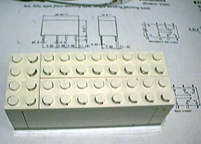
 First,
you should design your enclosure. For my design, I chose a 10
by 4 by 2.2 design. (2.2 = 2 bricks & 2 plates) this allows
my project to have all the connections on top. You can, of course,
design yours any way you see fit. Just make sure that your design
leaves enough room for the necessary components inside and that
the wires will have access to the electric plating. (The next
time I build one of these I will use a white technic beam in place
of one of the 1x8's. This will allow it to be attached to my creations
in a way similar to the RCX.)
First,
you should design your enclosure. For my design, I chose a 10
by 4 by 2.2 design. (2.2 = 2 bricks & 2 plates) this allows
my project to have all the connections on top. You can, of course,
design yours any way you see fit. Just make sure that your design
leaves enough room for the necessary components inside and that
the wires will have access to the electric plating. (The next
time I build one of these I will use a white technic beam in place
of one of the 1x8's. This will allow it to be attached to my creations
in a way similar to the RCX.)
For the rest of this document I will assume you are following
my general case design.
 Once
your enclosure is completed and you have performed a test fit
of all of the Lego components to ensure that they do not collapse
inward upon themselves it is time to design the circuit board.
Once
your enclosure is completed and you have performed a test fit
of all of the Lego components to ensure that they do not collapse
inward upon themselves it is time to design the circuit board.
 Measure
out the approximate dimensions of your enclosure and select the
most likely position for the circuit board. Then, cut the circuit
board to measure. It is important to test fit each of the components
to ensure they will fit properly on the circuit board and that
their dimensions will all fit in your enclosure. (Be sure to leave
adequate room for the wires that will be attached to the electric
plating.)
Measure
out the approximate dimensions of your enclosure and select the
most likely position for the circuit board. Then, cut the circuit
board to measure. It is important to test fit each of the components
to ensure they will fit properly on the circuit board and that
their dimensions will all fit in your enclosure. (Be sure to leave
adequate room for the wires that will be attached to the electric
plating.)
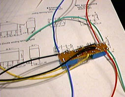
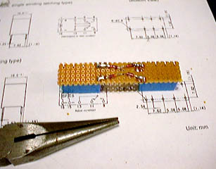 Now
solder the relays and diodes (observing the proper polarity) onto
the circuit board as seen in the picture. (Be sure to examine
the schematic before you begin so
you completely understand the procedure.)
Now
solder the relays and diodes (observing the proper polarity) onto
the circuit board as seen in the picture. (Be sure to examine
the schematic before you begin so
you completely understand the procedure.)
Once the above is completed you must attach a wire to each of
the opposing diode joinings. This is difficult to explain and
I strongly suggest you consult the schematic.
For this example I used a yellow wire. Once these wires are in
place you should test your relays to ensure that only one triggers
at a time depending on the polarity of the RCX. (I.e. Forward
or Reverse) If none or both trigger at the same time you have
a short or the relays/diodes are in the wrong orientation. It
is critical that this works as the schematic dictates.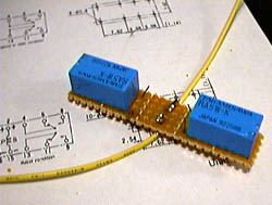
The two wires are then to be soldered to the 2 by 4 electric plating.
This is the input that triggers the device.
The (MS)2 Expander has three possible states.
Default state, bank one is active.
Positive power state, bank 2 is active.
Negative power state, bank 3 is active.
(The Positive and Negative banks depend on which way the device
is connected to the RCX output port)
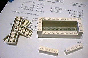
 The
inside wall of the 1 by 4 brick on which the above 2 by 4 electric
plate will sit must be removed. (See photo) This is to allow the
wires access to the plate and to allow the plate to sit firmly
in place. You must leave enough of this brick to allow proper
gluing.
The
inside wall of the 1 by 4 brick on which the above 2 by 4 electric
plate will sit must be removed. (See photo) This is to allow the
wires access to the plate and to allow the plate to sit firmly
in place. You must leave enough of this brick to allow proper
gluing.
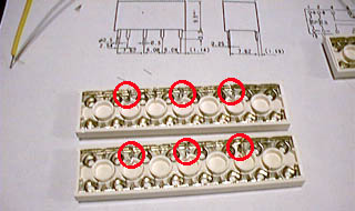 The
two 2 by 8 electric plating pieces must now have their respective
inside metal tracks cut in three places. Carefully cut the underside
metal on the inside track as seen in the photo. (This can be quite
difficult to achieve. Consult the sensor
pad project if you require a more detailed photo) The red
circled areas in the photo show the places that you must cut.
You MUST ensure that no current can get from one segment to the
other. It is imperative that this is done with extreme care. Cutting
the metal track is not an easy task.
The
two 2 by 8 electric plating pieces must now have their respective
inside metal tracks cut in three places. Carefully cut the underside
metal on the inside track as seen in the photo. (This can be quite
difficult to achieve. Consult the sensor
pad project if you require a more detailed photo) The red
circled areas in the photo show the places that you must cut.
You MUST ensure that no current can get from one segment to the
other. It is imperative that this is done with extreme care. Cutting
the metal track is not an easy task.
You may be wondering why you do not have to cut the outside metal
track on each of the two 2 by 8 electric plates. This is because
they are to be the common (or GROUND) connection. All three banks
will have this one connection in common. It is the active (or
HOT) connection with which we will be switching between the three
banks.
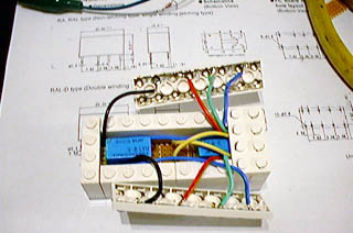 You
must now solder wires to each of the output pins on the relays.
(Please note the special configuration of the wiring going from
one relay to the other. This is how we do the default (bank 1)
state.) It is helpful here to use different colour wires. Make
sure you do the same for both sides. This will avoid confusion
in the future. Connect each of the wires to the inside segments
of the 2 by 8 electric plating. Please ensure that you put the
same bank in the same location on both sides to avoid confusion.
You
must now solder wires to each of the output pins on the relays.
(Please note the special configuration of the wiring going from
one relay to the other. This is how we do the default (bank 1)
state.) It is helpful here to use different colour wires. Make
sure you do the same for both sides. This will avoid confusion
in the future. Connect each of the wires to the inside segments
of the 2 by 8 electric plating. Please ensure that you put the
same bank in the same location on both sides to avoid confusion.
Once all six wires are firmly in place test to ensure that there
are no shorts between the plating segments and then test the relays
to ensure that the proper banks are active at the proper times.
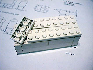
 Once
everything is functioning as it should be, perform a test fit
by putting everything into the enclosure and squeezing it together.
Re-test the entire device again.
Once
everything is functioning as it should be, perform a test fit
by putting everything into the enclosure and squeezing it together.
Re-test the entire device again.
Now carefully pry each segment apart one at a time, glue the device
together and allow it to dry. (Five-minute epoxy takes approximately
24 hours to fully harden)
Congratulations! You just created one of the most useful devices
I've designed to date.
That's about it, if you have any questions you may contact me
via email. Enjoy!
[RETURN] to TFM's Home Page