![]()
|
|
Resistor Switch Pad |
|
|---|
Just for the sake of having it, neither I nor this site have any affiliation with Lego, Lego group, Lego systems or Lego MindStorms. Also, I am not responsible for any damage to your RCX and/or computer that may result from the use of the knowledge/designs stored on this WebSite.
This is project two of the eight projects that I have thought
up so far.
This project was built on Nov. 2nd/1998. Sorry for it taking so
long to get on-line.
Now like most of you, you quickly discover that the three precious input sensors are too valuable to waste on mere switches. So I thought up other ways to allow more switches to be used with fewer ports. The project below is my answer to this dilemma.
 The logic behind this project was straightforward. You set the
port you wish to use to either raw (not available in the Official
MindStorms Software) or as a light sensor. for four switches each
with a different resistance value. Switch one has 5k resistance,
Switch two has 10k resistance, Switch three has 20k resistance,
& Switch four has 40k resistance. This gives you a total of
17 possible settings. (4 X 4 = 16 Plus 1 when used as an override
switch directly off the MS Pad)
The logic behind this project was straightforward. You set the
port you wish to use to either raw (not available in the Official
MindStorms Software) or as a light sensor. for four switches each
with a different resistance value. Switch one has 5k resistance,
Switch two has 10k resistance, Switch three has 20k resistance,
& Switch four has 40k resistance. This gives you a total of
17 possible settings. (4 X 4 = 16 Plus 1 when used as an override
switch directly off the MS Pad)
Of course, to get more inputs there is a trade-off of more work involved to check those inputs. Now, depending on your project there's no reason you have to use all four inputs. You can use as little as two (which has a total number of four possibilities)
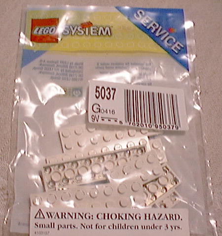 First, like my
last project (The temperature sensor), this project uses the LEGO
electric plating (part #5037) for the connector.
First, like my
last project (The temperature sensor), this project uses the LEGO
electric plating (part #5037) for the connector.
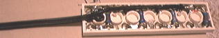
 Select
a 2x8 piece of electric plating and carefully cut the underside
metal as you see in the photo. The green dots indicate the power
start and end flow positions. (That's where the RCX will be connected
to in a later step) The RED shows where you should cut the underside.
That's two cuts on the bottom and one on the top. You should test
this with a multimeter to ensure the current cannot pass from
one section to the other. We're using a step pattern here to avoid
having to use any wires.
Select
a 2x8 piece of electric plating and carefully cut the underside
metal as you see in the photo. The green dots indicate the power
start and end flow positions. (That's where the RCX will be connected
to in a later step) The RED shows where you should cut the underside.
That's two cuts on the bottom and one on the top. You should test
this with a multimeter to ensure the current cannot pass from
one section to the other. We're using a step pattern here to avoid
having to use any wires.
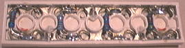 The
next step involves soldering the four resisters in place as you
can see in this photo. Basically, the resisters jump from the
lower track to the upper track to loop the current through all
four pads. Now it really doesn't matter what order the resister's
go in but to keep it all straight once it's together I suggest
going from least to most k's.
The
next step involves soldering the four resisters in place as you
can see in this photo. Basically, the resisters jump from the
lower track to the upper track to loop the current through all
four pads. Now it really doesn't matter what order the resister's
go in but to keep it all straight once it's together I suggest
going from least to most k's.
Once the four resisters are in place and you've tested the current flow with a multimeter, insuring there are no shorts between pads (that is other than the resisters themselves), it is time to attach the wire connector. For my project, I used one of the wires that came with the MindStorms kit. First, I cut off one end, leaving about one inch for a future project and then stripped the wires apart.
 Now
decide what end of your sensor pad you would like the wire to
come out of. In my example I chose the right end. (See photo)
this meant that one of my wires would have to be longer than the
other. I carefully planned out how my wire would run through the
inside of electric plating, trimming away the plastic as need
be. When I was sure of what I was doing, I cut and bared the wires.
I then proceeded to solder the wires to the appropriate ends of
the sensor pads and pressed the wires into place.
Now
decide what end of your sensor pad you would like the wire to
come out of. In my example I chose the right end. (See photo)
this meant that one of my wires would have to be longer than the
other. I carefully planned out how my wire would run through the
inside of electric plating, trimming away the plastic as need
be. When I was sure of what I was doing, I cut and bared the wires.
I then proceeded to solder the wires to the appropriate ends of
the sensor pads and pressed the wires into place.
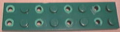 After
insuring the resisters and connector wires are connected as required
you may begin constructing the base plate. I chose green because
I have many of them, but you may choose whatever color you wish.
You now must carefully matchup your top plate with your bottom
one cutting away any of the knobs that will interfere with the
project. For my example some knobs I cut away entirely, others
I cut in half to allow someplace for the glue to stick.
After
insuring the resisters and connector wires are connected as required
you may begin constructing the base plate. I chose green because
I have many of them, but you may choose whatever color you wish.
You now must carefully matchup your top plate with your bottom
one cutting away any of the knobs that will interfere with the
project. For my example some knobs I cut away entirely, others
I cut in half to allow someplace for the glue to stick.
![]() Once
you have a good firm connection between the top and bottom plates,
glue with five-minute epoxy, crazy glue or some other such permanently
sticking substance. Hold the sensor pad together until the glue
dries.
Once
you have a good firm connection between the top and bottom plates,
glue with five-minute epoxy, crazy glue or some other such permanently
sticking substance. Hold the sensor pad together until the glue
dries.
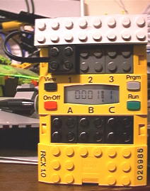
Do one final test with the multimeter before connecting it the RCX.
Congratulations! You have just built a four switch sensor Pad.
You must now test and record all 17 possibilities before you may begin programming for them.
Note: I have noticed that my sensor pad, in raw mode, sometimes duplicates other switch settings if the switches are not press down totally. I'm currently designing some new microswitch Lego compatible switches to avoid this problem in future.
 That's about it, if you have any questions you may contact me
via email. Enjoy!
That's about it, if you have any questions you may contact me
via email. Enjoy!
[RETURN] to TFM's Home Page